Category
- Products
-
- FAQ
- Contact us

AC Drive Manufacturer
Home » Applications » AC drive for boiler feed pump
AC drive for boiler feed pump
This application gives the perfect solution for the problem and operation conditions in water feeding system. With analysis and demonstration, we think the reform of AC drive could resolve these problems and make a good economic benefit.
Introduce
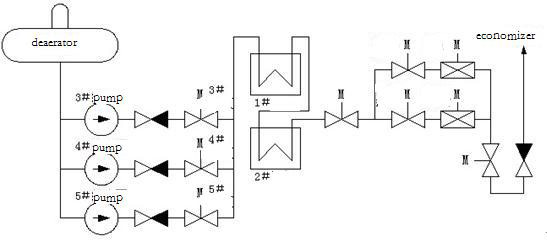
The 100MW boiler feed water system mainly consists of three 6kV/1600kW water feed pumps and high-low adjusting valve, high-pressure heaters and other equipment. The system configuration is shown as below. Water pump transfers water of deaerator finally into boil-bag by high-pressure heater. Usually, the system adjusts the opening of gate according to load, achieving the purpose of water level stability. The system has the following questions:
Selection for system solutions
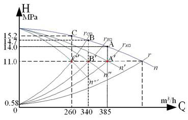
As the system is in mode of two work one spare, so we consider to use one in direct on line, one in variable frequency or both in variable frequency. The original H-Q curve shown in Figure 1. The two pumps curve combine into n. On load of 100 MW, the pipe network characteristic is rA'. The work point is A when the valve is fully open. Using valve control, the available point is A when the opening is decreasing. It means the boiler system only needs 11.0Mpa in 100MW load, flow 385m3. The active power of two pumps is PA'. It is corresponding area with"A'-385-0-11.0", and the "A- A'-11.0-14.0" is consumed by valve throttle. The operation conditions of 90MW and 70MW are the same as 100MW. From figure 1, less flow, more throttle loss and lower efficiency.
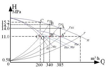
If the system adopts mode of one in direct on line, one in variable frequency, with valve full open, H-Q curve of variable frequency pump is shown n0. In 100MW load, characteristic is rA', the direct on line pump curve is n0, actual pressure is 11.0Mpa, the effective displacement is 270m3/h corresponding to O. After another pump runs in variable frequency, the speed is down. Its curve is nA '. Work point is A'. Active power of pump is PA'. There is no throttle loss any more. But when the load is 70MW, flow 260 m3/h is less than rated flow 270m3/h. The variable frequency pump can not meet control demand. At this moment, stop line frequency pump and make variable frequency pump meet the system requirements. But one pump operation greatly reduces the safety of the system, it is infeasible.
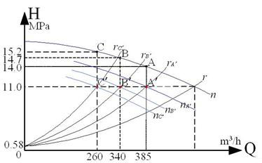
In mode of direct on line &variable frequency operation, throttle adjustment must be used when load is down. Then, the variable frequency pump should make outlet pressure equal to pipe network. The output flow is 0, the operation curve is nC'. The whole efficiency is reduced; and this mode causes system complex, makes against for peak adjustment. Long term running at full load will influence the lifetime of equipment. Therefore, this mode is not suitable for boiler water pump system.
For the above reasons, the system should adopt the two pumps in variable frequency.
System Solutions
By researching and analyzing the problem in the original system, we design the reform in order to "ensure safe system, reliable structure, best cost-effective program",
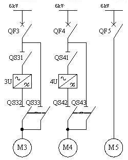
The system adopts mode of one drive one. The main electrical principle of system is shown in figure.
Economic Benefit Analysis
1. Field data
1) Generator Capacity: 100MW
2) Number of feed-water pump: 3 (Two work and one spare)
3) Data of pump:
4) Data of motor:
5) The parameter statistics in different loads
6) Cost price: 0.232yuan/kW.h
7) Annual working hours: 8061h
2. The annual power consumption in direct on line state:
Pd: Motor power; d: Motor efficiency; U: Input Voltage; cosφ: Power factor.
Formula: Pd =1.732×U×I×cosφ… ①
Form ①, cosφ=0.87.
The percentage of average running time=The average running time/24
①The actual power consumption is shown in the below table.
Cd: Annual power consumption; T: Running time of year; δ: The percentage of single-load run time.
The formula of annual power consumption: Cd= T×∑ (Pd×δ) …②
Cd =8061× (2712.31×25%+2531.49×41.7%+2441.08×33.3%)=20527817 kW.h
Therefore, the total power of two pumps in direct on line is 20527817 kW.h.
3. The annual power consumption in variable frequency state:
1) The pressure of feed pump:
Resistance of pipe net=Outlet pressure of pump-Inlet pressure of gate
The pressure in the valve full opening=The outlet pressure of gate+Resistance of pipe net
Work pressure of feed pump= The pressure in the valve full opening-Inlet pressure of pump
According to above, we could know the work pressure of feed pump.
2. The pump characteristics in different loads:
3) The power consumption of feed pump in variable frequency:
Pd': Shaft Power of motor; P: Shaft Power of pump; Motor efficiency; f: Actual efficiency of AC drive; Pump efficiency; Q: Output flow; H: Pressure; λ: Characteristics
Pd'= P …③
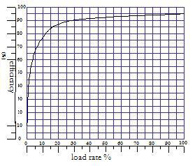
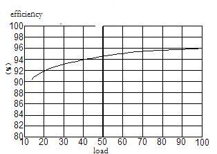
The relationship between motor efficiency and β is shown as figure .
Shaft Power of pump: P=λ.Q*H
Motor power: Pd=Pd'/ηd
we know: λ/ηd=Pd / (Q*H); Pd=λ'.Q*H
Line side power consumption: Pb=Pd / ηf
Cb=8061× (2340.38×25%+2097.76×41.7%+1938.78×33.3%)= 16972241kW.h
Therefore, the total annual power consumption of condensation pump in variable frequency is 16972241kW.h
4. Calculation of Energy Saving:
The benefit of reform is not only the economy saving but also with many indirect economic advantages.
Annual energy saving: ΔC= Cd-Cb =3556000 kW.h
Saving Ratio : (ΔC/Cd)×100% = (355.6/ 2052.8)×100% =17.3%
Annual cost saved: 355.6×0.232=825000 RMB (USD 121323)
Conclusion
The reform of the two pumps by AC drive is feasible. It could achieve the purpose of reducing the rate of plant power consumption, also good for system security, reliability, maintenance and other aspects.
Introduce
The 100MW boiler feed water system mainly consists of three 6kV/1600kW water feed pumps and high-low adjusting valve, high-pressure heaters and other equipment. The system configuration is shown as below. Water pump transfers water of deaerator finally into boil-bag by high-pressure heater. Usually, the system adjusts the opening of gate according to load, achieving the purpose of water level stability. The system has the following questions:

- The pump runs in constant speed with great throttle loss, a high pressure on outlet, serious damage on pipe, low efficiency and a waste of energy.
- When the flow is decreasing and the opening is down, increasing pressure differential makes low safety and a big loss in pressure, causing more energy consumption.
- Long term opening in 40~70% accelerates wear and tear of the valve, leading to bad valve control features.
- The high pressure of pipe net threatens sealing of the system seriously, leading to valve leakage.
- Short service time, large routine maintenance and high cost in maintenance cause a tremendous waste of resources.
Selection for system solutions
As the system is in mode of two work one spare, so we consider to use one in direct on line, one in variable frequency or both in variable frequency. The original H-Q curve shown in Figure 1. The two pumps curve combine into n. On load of 100 MW, the pipe network characteristic is rA'. The work point is A when the valve is fully open. Using valve control, the available point is A when the opening is decreasing. It means the boiler system only needs 11.0Mpa in 100MW load, flow 385m3. The active power of two pumps is PA'. It is corresponding area with"A'-385-0-11.0", and the "A- A'-11.0-14.0" is consumed by valve throttle. The operation conditions of 90MW and 70MW are the same as 100MW. From figure 1, less flow, more throttle loss and lower efficiency.
If the system adopts mode of one in direct on line, one in variable frequency, with valve full open, H-Q curve of variable frequency pump is shown n0. In 100MW load, characteristic is rA', the direct on line pump curve is n0, actual pressure is 11.0Mpa, the effective displacement is 270m3/h corresponding to O. After another pump runs in variable frequency, the speed is down. Its curve is nA '. Work point is A'. Active power of pump is PA'. There is no throttle loss any more. But when the load is 70MW, flow 260 m3/h is less than rated flow 270m3/h. The variable frequency pump can not meet control demand. At this moment, stop line frequency pump and make variable frequency pump meet the system requirements. But one pump operation greatly reduces the safety of the system, it is infeasible.
In mode of direct on line &variable frequency operation, throttle adjustment must be used when load is down. Then, the variable frequency pump should make outlet pressure equal to pipe network. The output flow is 0, the operation curve is nC'. The whole efficiency is reduced; and this mode causes system complex, makes against for peak adjustment. Long term running at full load will influence the lifetime of equipment. Therefore, this mode is not suitable for boiler water pump system.


For the above reasons, the system should adopt the two pumps in variable frequency.
System Solutions
By researching and analyzing the problem in the original system, we design the reform in order to "ensure safe system, reliable structure, best cost-effective program",
The system adopts mode of one drive one. The main electrical principle of system is shown in figure.

Economic Benefit Analysis
1. Field data
1) Generator Capacity: 100MW
2) Number of feed-water pump: 3 (Two work and one spare)
3) Data of pump:
| Model | ZDG-10 | Power (P) | 1474 kW |
| Rated flow (qv,max) | 270 m3/h | Efficiency (η) | 0.756 |
| Rated water lift (H) | 1515 m | Speed (r/min) | 2980 |
4) Data of motor:
| Model | YK1600-2/990 | Rated voltage (U0) | 6 kV |
| Rated power (Pdn) | 1600 kW | Efficiency (η) | 94% |
| Rated current (I0) | 177A | Power factor (cosφ) |
|
| Speed (n0) | 2981 r/min |
|
|
5) The parameter statistics in different loads
| Load (MW) | 100 | 90 | 70 |
| Gate opening (%) | 30~70 | 30~70 | 30~70 |
| Inlet pressure of pump (MPa) | 0.6 | 0.6 | 0.6 |
| Outlet pressure of pump (MPa) | 14.0 | 14.7 | 15.2 |
| Inlet pressure of gate (MPa) | 13 | 13.5 | 14 |
| outlet pressure of gate (MPa) | 11.0 | 11.0 | 11.0 |
| Flow (t/h) | 385 | 340 | 260 |
| Motor current (A) | 150/150 | 140/140 | 135/135 |
| The average running time (h/d) | 6 | 10 | 8 |
6) Cost price: 0.232yuan/kW.h
7) Annual working hours: 8061h
2. The annual power consumption in direct on line state:
Pd: Motor power; d: Motor efficiency; U: Input Voltage; cosφ: Power factor.
Formula: Pd =1.732×U×I×cosφ… ①
Form ①, cosφ=0.87.
The percentage of average running time=The average running time/24
①The actual power consumption is shown in the below table.
| Generator Power (MW) | 100 | 90 | 70 |
| Flow (t/h) | 385 | 340 | 260 |
| Motor current (A) | 150 | 140 | 135 |
| the total power consumption of two pumps (kW) | 2712.31 | 2531.49 | 2441.08 |
| The percentage of the average running time (%) | 25.0 | 41.7 | 33.3 |
Cd: Annual power consumption; T: Running time of year; δ: The percentage of single-load run time.
The formula of annual power consumption: Cd= T×∑ (Pd×δ) …②
Cd =8061× (2712.31×25%+2531.49×41.7%+2441.08×33.3%)=20527817 kW.h
Therefore, the total power of two pumps in direct on line is 20527817 kW.h.
3. The annual power consumption in variable frequency state:
1) The pressure of feed pump:
Resistance of pipe net=Outlet pressure of pump-Inlet pressure of gate
The pressure in the valve full opening=The outlet pressure of gate+Resistance of pipe net
Work pressure of feed pump= The pressure in the valve full opening-Inlet pressure of pump
According to above, we could know the work pressure of feed pump.
| Generator Load (MW) | 100 | 90 | 70 |
| Inlet pressure of pump (MPa) | 0.6 | 0.6 | 0.6 |
| Outlet pressure of pump (MPa) | 14 | 14.7 | 15.2 |
| Inleput pressure of gate (MPa) | 13.3 | 14 | 14.7 |
| Outlet pressure of pump (MPa) | 11 | 11 | 11 |
| The pressure of valve full opening (MPa) | 11.7 | 11.7 | 11.5 |
| Work pressure of variable frequency pump (MPa) | 11.1 | 11.1 | 10.9 |
2. The pump characteristics in different loads:
| Generator Load (MW) | 100 | 90 | 70 |
| Inlet pressure of pump (MPa) | 0.6 | 0.6 | 0.6 |
| Outlet pressure of pump (MPa) | 14 | 14.7 | 15.2 |
| Work pressure in direct on line (MPa) | 13.4 | 14.1 | 14.6 |
| Flow (t/h) | 385 | 340 | 260 |
| Total power (kW) | 2712.31 | 2531.49 | 2441.08 |
| Characteristic λ | 0.53 | 0.53 | 0.64 |
3) The power consumption of feed pump in variable frequency:
Pd': Shaft Power of motor; P: Shaft Power of pump; Motor efficiency; f: Actual efficiency of AC drive; Pump efficiency; Q: Output flow; H: Pressure; λ: Characteristics
Pd'= P …③
The relationship between motor efficiency and β is shown as figure .


Shaft Power of pump: P=λ.Q*H
Motor power: Pd=Pd'/ηd
we know: λ/ηd=Pd / (Q*H); Pd=λ'.Q*H
Line side power consumption: Pb=Pd / ηf
| Generator Load (MW) | 100 | 90 | 70 |
| Work pressure of feed pump (MPa) | 11.1 | 11.1 | 10.9 |
| Flow (t/h) | 385 | 340 | 260 |
| Characteristic λ | 0.53 | 0.53 | 0.64 |
| Total power consumption (kW) | 2307.49 | 2082.65 | 1906.05 |
| Efficiency of converter | 0.96 | 0.95 | 0.94 |
| Line side power consumption (kW) | 2340.38 | 2097.76 | 1938.78 |
| The percentage of the average running time (%) | 25.0 | 41.7 | 33.3 |
Cb=8061× (2340.38×25%+2097.76×41.7%+1938.78×33.3%)= 16972241kW.h
Therefore, the total annual power consumption of condensation pump in variable frequency is 16972241kW.h
4. Calculation of Energy Saving:
The benefit of reform is not only the economy saving but also with many indirect economic advantages.
Annual energy saving: ΔC= Cd-Cb =3556000 kW.h
Saving Ratio : (ΔC/Cd)×100% = (355.6/ 2052.8)×100% =17.3%
Annual cost saved: 355.6×0.232=825000 RMB (USD 121323)
- Eliminate the grid voltage fluctuation when the motor starts.
- Eliminate the damage to motor when the motor starts at a large current.
- Increase the lifetime of motor, pipe and valve, reduces the workload of maintenance and costs.
- Improve the stability of the system automatic device. Provide a reliable guarantee for economy operation of system. The system operating parameters is improved, make the system efficiency higher.
Conclusion
The reform of the two pumps by AC drive is feasible. It could achieve the purpose of reducing the rate of plant power consumption, also good for system security, reliability, maintenance and other aspects.
Post a Comment:
You may also like:

