Category
- Products
-
- FAQ
- Contact us

AC Drive Manufacturer
AC Drives Basics (Benefits, Principle and Theory)
AC drive usage has increased dramatically in HVAC applications. The AC drives are now commonly applied to air handlers, pumps, chillers and tower fans. A better understanding of AC drives will lead to improved application and selection of both equipment and HVAC systems. This article is intended to provide a basic understanding of AC drive operation principle and theory, and AC drive benefits.
AC Drive Operation
Understanding the basic principles and theory behind AC drive operation requires understanding the three basic sections of the AC drive: the rectifier, dc bus, and inverter.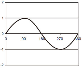
The voltage on an alternating current (ac) power supply rises and falls in the pattern of a sine wave (see Figure 1). When the voltage is positive, current flows in one direction; when the voltage is negative, the current flows in the opposite direction. This type of power system enables large amounts of energy to be efficiently transmitted over great distances.
The rectifier in an AC drive is used to convert incoming ac power into direct current (dc) power. One rectifier will allow power to pass through only when the voltage is positive. A second rectifier will allow power to pass through only when the voltage is negative. Two rectifiers are required for each phase of power. Since most large power supplies are three phase, there will be a minimum of 6 rectifiers used (see Figure 2). Appropriately, the term "6 pulse" is used to describe a variable frequency drive with 6 rectifiers. An AC drive may have multiple rectifier sections, with 6 rectifiers per section, enabling an AC drive to be "12 pulse," "18 pulse," or "24 pulse." The benefit of "multi-pulse" AC drives will be described later in the harmonics section.
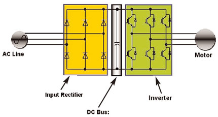
Fig. 2. AC drive basics: Existing technology
Rectifiers may utilize diodes, silicon controlled rectifiers (SCR), or transistors to rectify power. Diodes are the simplest device and allow power to flow any time voltage is of the proper polarity. Silicon controlled rectifiers include a gate circuit that enables a microprocessor to control when the power may begin to flow, making this type of rectifier useful for solid-state starters as well. Transistors include a gate circuit that enables a microprocessor to open or close at any time, making the transistor the most useful device of the three. An AC drive using transistors in the rectifier section is said to have an "active front end."
After the power flows through the rectifiers it is stored on a dc bus. The dc bus contains capacitors to accept power from the rectifier, store it, and later deliver that power through the inverter section. The dc bus may also contain inductors, dc links, chokes, or similar items that add inductance, thereby smoothing the incoming power supply to the dc bus. The final section of the AC drive is referred to as an inverter. The inverter contains transistors that deliver power to the motor. The "Insulated Gate Bipolar Transistor" (IGBT) is a common selection in modern AC drives. The IGBT can switch on and off several thousand times per second and precisely control the power delivered to the motor. The IGBT uses a method named "pulse width modulation" (PWM) to simulate a current sine wave at the desired frequency to the motor.
Motor speed (rpm) is dependent upon frequency. Varying the frequency output of the AC drive controls motor speed:
As AC drive usage in HVAC applications has increased, fans, pumps, air handlers, and chillers can benefit from speed control. AC drives provide the following basic advantages:
AC Drive Capacity Control Saves Energy
In theory, most applications do not require a constant flow of a fluid. Equipment is sized for a peak load that may account for only 1% of the hours of operation. The remaining hours of operation need only a fraction of the flow. Traditionally, devices that throttle output have been employed to reduce the flow. However, when compared with speed control, these methods are significantly less efficient.
Mechanical Capacity Control
Throttling valves, vanes, or dampers may be employed to control capacity of a constant speed pump or fan. These devices increase the head, thereby forcing the fan or pump to ride the curve to a point where it produces less flow (Figure 3). Power consumption is the product of head and flow. Throttling the output increases head, but reduces flow, and provides some energy savings.
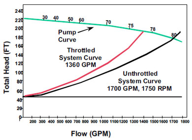
Fig. 3. Mechanical capacity control
Variable Speed Capacity Control
For centrifugal pumps, fans and compressors, the ideal fan (affinity) laws describe how speed affects flow, head and power consumption (Table A).
Table A. Effects of Changes in Fan Speed
Assumes fluid is fresh water, (specific gravity = 1).
When using speed to reduce capacity, both the head and flow are reduced, maximizing the energy savings. A basic comparison of mechanical and speed control for capacity reduction (Figure 4) shows that variable speed is the most efficient means of capacity control.
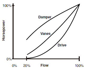
Fig. 4. Comparison of mechanical capacity control and speed capacity control
Low Inrush Motor Starting
Motor manufacturers face difficult design choices. Designs optimized for low starting current often sacrifice efficiency, power factor, size, and cost. With these considerations in mind, it is common for AC induction motors to draw 6 to 8 times their full load amps when they are started across the line. When large amounts of current are drawn on the transformers, a voltage drop can occur, adversely affecting other equipment on the same electrical system. Some voltage sensitive applications may even trip off line. For this reason, many engineers specify a means of reducing the starting current of large AC induction motors.
Soft Starters
Wye-delta, part winding, autotransformer, and solidstate starters are often used to reduce inrush during motor starting. All of these starters deliver power to the motor at a constant frequency and therefore must limit the current by controlling the voltage supplied to the motor. Wye delta, part winding, and autotransformer starters use special electrical connections to reduce the voltage. Solid-state starters use SCRs to reduce the voltage. The amount of voltage reduction possible is limited because the motor needs enough voltage to generate torque to accelerate. With maximum allowable voltage reduction, the motor will still draw two to four times the full load amps (FLA) during starting. Additionally, rapid acceleration associated with wye-delta starters can wear belts and other power transmission components.
AC drives as Starters
An AC drive is the ideal soft starter since it provides the lowest inrush of any starter type as shown in Table B. Unlike all other types of starters, the AC drive can use frequency to limit the power and current delivered to the motor. The AC drive will start the motor by delivering power at a low frequency. At this low frequency, the motor does not require a high level of current. The AC drive incrementally increases the frequency and motor speed until the desired speed is met. The current level of the motor never exceeds the full load amp rating of the motor at any time during its start or operation. In addition to the benefit of low starting current, motor designs can now be optimized for high efficiency.
Table B. Comparison of Starter Types Base on Inrush
Easy Installation
Many pieces of equipment are factory shipped with unit mounted AC drives that arrive pre-programmed and factory wired. Motor leads, control power for auxiliaries, and communication lines are all factory wired. The AC drive cooling lines on unit-mounted chiller AC drives are also factory installed. The installing contractor needs only to connect the line power supply to the AC drive.
High Power Factor
Power converted to motion, heat, sound, etc. is called real power and is measured in kilowatts (kW). Power that charges capacitors or builds magnetic fields is called reactive power and is measured in Kilovolts Amps Reactive (kVAR). The vector sum of the kW and the kVAR is the Total Power (energy) and is measured in Kilovolt Amperes (KVA) (Figure 5). Power factor is the ratio of kW/KVA.
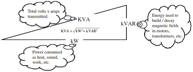
Fig. 5. Measuring power
Motors draw reactive current to support their magnetic fields in order to cause rotation. Excessive reactive current is undesirable because it creates additional resistance losses and can require the use of larger transformers and wires. In addition, utilities often penalize owners for low power factor. Decreasing reactive current will increase power factor.
Typical AC motors may have a full load power factor ranging from 0.84 to 0.88. As the motor load is reduced, the power factor becomes lower. Utilities may require site power factor values ranging from 0.85 to 0.95 and impose penalties to enforce this requirement. Power factor correction capacitors can be added to reduce the reactive current measured upstream of the capacitors and increase the measured power factor. To prevent damage to the motor, power factor correction capacitors should not exceed the motor manufacturer's recommendations. In most cases, this results in maximum corrected values of 0.90 to 0.95.
The AC drives include capacitors in the DC Bus that perform the same function and maintain high power factor on the line side of the AC drive. This eliminates the need to add power factor correction equipment to the motor or use expensive capacitor banks. In addition, AC drives often result in higher line side power factor values than constant speed motors equipped with correction capacitors.
Low Full Load KVA
Total Power (KVA) is often the limiting factor in the amount of energy that can be transmitted through an electrical device or system. If the KVA required by equipment can be reduced during periods of peak demand, it will help alleviate voltage sags, brown outs, and power outages. The unit efficiency and power factor are equally weighted when calculating KVA. Therefore, equipment that may be equal or worse in efficiency, but higher in power factor has significantly lower KVA (Table C).
Table C. Power Factors and Energy Usage
NOTE: KVA = Volts x Amps x 1.732
In this example, equipment with a higher power factor uses 15% less KVA while performing the same job. This can lower electrical system cost on new projects and free up KVA capacity on existing systems.
Backup generators are typically sized to closely match the load. Lowering KVA can reduce the size of the generator required. When AC drives with active front ends are used, the generator size can approach an ideal 1:1 ratio of kW/KVA because the power factor is near unity (1.0) and the harmonics produced by the AC drive are extremely low.
Lower KVA also benefits utilities. When the power factor is higher, more power (kW) can be delivered through the same transmission equipment.
Conclusion
The advantages by using AC drives:
AC Drive Operation
Understanding the basic principles and theory behind AC drive operation requires understanding the three basic sections of the AC drive: the rectifier, dc bus, and inverter.

The voltage on an alternating current (ac) power supply rises and falls in the pattern of a sine wave (see Figure 1). When the voltage is positive, current flows in one direction; when the voltage is negative, the current flows in the opposite direction. This type of power system enables large amounts of energy to be efficiently transmitted over great distances.
The rectifier in an AC drive is used to convert incoming ac power into direct current (dc) power. One rectifier will allow power to pass through only when the voltage is positive. A second rectifier will allow power to pass through only when the voltage is negative. Two rectifiers are required for each phase of power. Since most large power supplies are three phase, there will be a minimum of 6 rectifiers used (see Figure 2). Appropriately, the term "6 pulse" is used to describe a variable frequency drive with 6 rectifiers. An AC drive may have multiple rectifier sections, with 6 rectifiers per section, enabling an AC drive to be "12 pulse," "18 pulse," or "24 pulse." The benefit of "multi-pulse" AC drives will be described later in the harmonics section.

Fig. 2. AC drive basics: Existing technology
Rectifiers may utilize diodes, silicon controlled rectifiers (SCR), or transistors to rectify power. Diodes are the simplest device and allow power to flow any time voltage is of the proper polarity. Silicon controlled rectifiers include a gate circuit that enables a microprocessor to control when the power may begin to flow, making this type of rectifier useful for solid-state starters as well. Transistors include a gate circuit that enables a microprocessor to open or close at any time, making the transistor the most useful device of the three. An AC drive using transistors in the rectifier section is said to have an "active front end."
After the power flows through the rectifiers it is stored on a dc bus. The dc bus contains capacitors to accept power from the rectifier, store it, and later deliver that power through the inverter section. The dc bus may also contain inductors, dc links, chokes, or similar items that add inductance, thereby smoothing the incoming power supply to the dc bus. The final section of the AC drive is referred to as an inverter. The inverter contains transistors that deliver power to the motor. The "Insulated Gate Bipolar Transistor" (IGBT) is a common selection in modern AC drives. The IGBT can switch on and off several thousand times per second and precisely control the power delivered to the motor. The IGBT uses a method named "pulse width modulation" (PWM) to simulate a current sine wave at the desired frequency to the motor.
Motor speed (rpm) is dependent upon frequency. Varying the frequency output of the AC drive controls motor speed:
Speed (rpm) = frequency (hertz) x 120 / no. of polesExample:
2-pole motor at different frequencies
3600 rpm = 60 hertz x 120 / 2 = 3600 rpm
3000 rpm = 50 hertz x 120 / 2 = 3000 rpm
2400 rpm = 40 hertz x 120 / 2 = 2400 rpm
Benefits of AC drive
As AC drive usage in HVAC applications has increased, fans, pumps, air handlers, and chillers can benefit from speed control. AC drives provide the following basic advantages:
- energy savings
- low motor starting current
- reduction of thermal and mechanical stresses on motors and belts during starts
- simple installation
- high power factor
- lower KVA
AC Drive Capacity Control Saves Energy
In theory, most applications do not require a constant flow of a fluid. Equipment is sized for a peak load that may account for only 1% of the hours of operation. The remaining hours of operation need only a fraction of the flow. Traditionally, devices that throttle output have been employed to reduce the flow. However, when compared with speed control, these methods are significantly less efficient.
Mechanical Capacity Control
Throttling valves, vanes, or dampers may be employed to control capacity of a constant speed pump or fan. These devices increase the head, thereby forcing the fan or pump to ride the curve to a point where it produces less flow (Figure 3). Power consumption is the product of head and flow. Throttling the output increases head, but reduces flow, and provides some energy savings.

Fig. 3. Mechanical capacity control
Variable Speed Capacity Control
For centrifugal pumps, fans and compressors, the ideal fan (affinity) laws describe how speed affects flow, head and power consumption (Table A).
Table A. Effects of Changes in Fan Speed
|
Flow changes linearly with speed |
Flow Rate2 = Flow Rate1 x (RPM2/RPM1) |
|
Head varies as the speed squared |
Lift2 = Lift1 x (RPM2/RPM1)2 |
|
Power varies as the speed cubed |
Power2 = Power1 x (RPM2/RPM1)3 |
When using speed to reduce capacity, both the head and flow are reduced, maximizing the energy savings. A basic comparison of mechanical and speed control for capacity reduction (Figure 4) shows that variable speed is the most efficient means of capacity control.

Fig. 4. Comparison of mechanical capacity control and speed capacity control
Low Inrush Motor Starting
Motor manufacturers face difficult design choices. Designs optimized for low starting current often sacrifice efficiency, power factor, size, and cost. With these considerations in mind, it is common for AC induction motors to draw 6 to 8 times their full load amps when they are started across the line. When large amounts of current are drawn on the transformers, a voltage drop can occur, adversely affecting other equipment on the same electrical system. Some voltage sensitive applications may even trip off line. For this reason, many engineers specify a means of reducing the starting current of large AC induction motors.
Soft Starters
Wye-delta, part winding, autotransformer, and solidstate starters are often used to reduce inrush during motor starting. All of these starters deliver power to the motor at a constant frequency and therefore must limit the current by controlling the voltage supplied to the motor. Wye delta, part winding, and autotransformer starters use special electrical connections to reduce the voltage. Solid-state starters use SCRs to reduce the voltage. The amount of voltage reduction possible is limited because the motor needs enough voltage to generate torque to accelerate. With maximum allowable voltage reduction, the motor will still draw two to four times the full load amps (FLA) during starting. Additionally, rapid acceleration associated with wye-delta starters can wear belts and other power transmission components.
AC drives as Starters
An AC drive is the ideal soft starter since it provides the lowest inrush of any starter type as shown in Table B. Unlike all other types of starters, the AC drive can use frequency to limit the power and current delivered to the motor. The AC drive will start the motor by delivering power at a low frequency. At this low frequency, the motor does not require a high level of current. The AC drive incrementally increases the frequency and motor speed until the desired speed is met. The current level of the motor never exceeds the full load amp rating of the motor at any time during its start or operation. In addition to the benefit of low starting current, motor designs can now be optimized for high efficiency.
Table B. Comparison of Starter Types Base on Inrush
|
Starter Type |
Starting Current (% of FLA) |
|
AC Drive |
100% |
|
Wye-Delta Starter |
200-275% |
|
Solid State Soft Starter |
200% |
|
Autotransformer Starter |
400-500% |
|
Part Winding Starter |
400-500% |
|
Across the Line Starter |
600-800% |
Easy Installation
Many pieces of equipment are factory shipped with unit mounted AC drives that arrive pre-programmed and factory wired. Motor leads, control power for auxiliaries, and communication lines are all factory wired. The AC drive cooling lines on unit-mounted chiller AC drives are also factory installed. The installing contractor needs only to connect the line power supply to the AC drive.
High Power Factor
Power converted to motion, heat, sound, etc. is called real power and is measured in kilowatts (kW). Power that charges capacitors or builds magnetic fields is called reactive power and is measured in Kilovolts Amps Reactive (kVAR). The vector sum of the kW and the kVAR is the Total Power (energy) and is measured in Kilovolt Amperes (KVA) (Figure 5). Power factor is the ratio of kW/KVA.

Fig. 5. Measuring power
Motors draw reactive current to support their magnetic fields in order to cause rotation. Excessive reactive current is undesirable because it creates additional resistance losses and can require the use of larger transformers and wires. In addition, utilities often penalize owners for low power factor. Decreasing reactive current will increase power factor.
Typical AC motors may have a full load power factor ranging from 0.84 to 0.88. As the motor load is reduced, the power factor becomes lower. Utilities may require site power factor values ranging from 0.85 to 0.95 and impose penalties to enforce this requirement. Power factor correction capacitors can be added to reduce the reactive current measured upstream of the capacitors and increase the measured power factor. To prevent damage to the motor, power factor correction capacitors should not exceed the motor manufacturer's recommendations. In most cases, this results in maximum corrected values of 0.90 to 0.95.
The AC drives include capacitors in the DC Bus that perform the same function and maintain high power factor on the line side of the AC drive. This eliminates the need to add power factor correction equipment to the motor or use expensive capacitor banks. In addition, AC drives often result in higher line side power factor values than constant speed motors equipped with correction capacitors.
Low Full Load KVA
Total Power (KVA) is often the limiting factor in the amount of energy that can be transmitted through an electrical device or system. If the KVA required by equipment can be reduced during periods of peak demand, it will help alleviate voltage sags, brown outs, and power outages. The unit efficiency and power factor are equally weighted when calculating KVA. Therefore, equipment that may be equal or worse in efficiency, but higher in power factor has significantly lower KVA (Table C).
Table C. Power Factors and Energy Usage
|
Input kW |
Power Factor |
Amps |
Volts |
KVA |
|
350.4 |
.84 |
502 |
Nominal 480 |
417 |
|
350.4 |
.99 |
426 |
Nominal 480 |
354 |
In this example, equipment with a higher power factor uses 15% less KVA while performing the same job. This can lower electrical system cost on new projects and free up KVA capacity on existing systems.
Backup generators are typically sized to closely match the load. Lowering KVA can reduce the size of the generator required. When AC drives with active front ends are used, the generator size can approach an ideal 1:1 ratio of kW/KVA because the power factor is near unity (1.0) and the harmonics produced by the AC drive are extremely low.
Lower KVA also benefits utilities. When the power factor is higher, more power (kW) can be delivered through the same transmission equipment.
Conclusion
The advantages by using AC drives:
- AC drives provide the most energy efficient means of capacity control.
- AC drives have the lowest starting current of any starter type.
- AC drives reduce thermal and mechanical stresses on motors and belts.
- AC drive installation is as simple as connecting the power supply to the AC drive.
- AC drives with AFE technology can meet even the most stringent harmonic standards and reduce backup generator sizing.
- AC drives provide high power factor, eliminating the need for external power factor correction capacitors.
- AC drives provide lower KVA, helping alleviate voltage sags and power outages.
Post a Comment:
You may also like:

