Category
- Products
-
- FAQ
- Contact us

AC Drive Manufacturer
Home » Applications » AC Drives for ID Fan system
AC Drives for ID Fan system
This paper introduced principal, function and characteristics of AC drive coordination control technology, explains a new method of energy saving without modification for DCS and control logics.
A 100MW machinery unit is 380t/h coal powder furnace. The ID fan system is driven by two motors 6kV/800kW. In order to save energy, improve ID fan efficiency, reduce damper adjustment loss, user decides to choose stable and reliable AC drive reconstruction.
Because the DCS was changed for several times, the spare I/O ports are not enough for AC drive construction. There is a question that how to realize AC drive reconstruction without modification for DCS and control logic.
After deep research in AC drive characteristics, furnace operation technology and DCS structure, we put forward a new technology (HCU for abbreviation) which can save energy without modification for DCS and control logic.
Scheme
After analyzing furnace ID fan system, according to tenet of "safe and reliable, appropriate structure, easy operation, few change", we provide a one-drive-one manual bypass scheme. Please see following drawing:
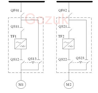
QF: MV switch; QS: isolating switch; TF: AC drive; M; motor. Dashed border inside is newly added. QF and M are original equipments. QS12 and QS13 are mechanical and electrical interlocked to prevent AC drive output from being short circuit with 6kV. When ID fan needs to run in variable state, user closes QS11 and starts ID fan; when ID fan needs to run in direct on line state, user stops ID fan, opens QS12 and QS11, closes QS13, starts ID fan.
Principle
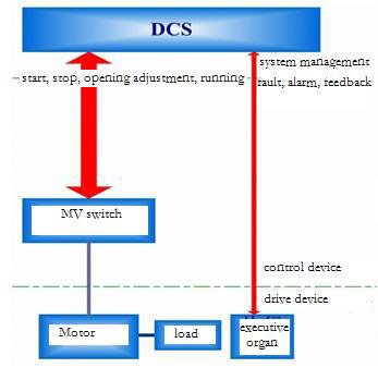
Before reconstruction, original control drawing is shown in following figure. DCS controls ID motor start/stop by controlling MV switch, controls furnace pressure by adjusting damper opening.
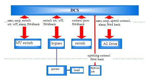
After reconstruction with AC drive, for routine design, it needs to add AC drive, bypass cabinet, switch equipment to connect control signals and status signals to DCS, realizing equipment control and variable frequency operation by changing DCS port and logic. Please see control principle drawing:
HCU technology is obvious simple in system structure, control logic and DCS ports. System configures MV switch, AC drive as a whole equipment through HCU, same function with original system, realizing ID fan start/stop and requirement of furnace pressure. HCU identifies fan operation mode according to dynamic system state, receives DCS start/stop signal for motor. Meanwhile, HCU coordinates speed, opening and pressure signal automatically as per operation mode. In this way, control characteristic keeps the same as present system, no need of changing DCS port, inside logic and interlock.
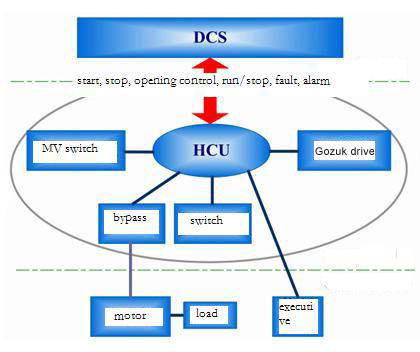
HCU configures AC drive, bypass cabinet and MV switch as a whole equipment, namely, for DCS, there is no problem of switch between variable frequency/direct on line, speed switch, opening switch, and interlock logic modification. Because ports between DCS and ID fan control device is not changed, original interlock and protection logic are still valid. HCU can identify fault points and security class automatically according to operation mode and equipment status, ensure correct signal to DCS, avoid mistake and no response.
Implementation
Before reconstruction, DCS communicates with control ports of ID fan, MV switch and other control devices. Its drawing is shown in figure 5. after reconstruction, DCS manages signals, distributes commands and controls objects through HCU. Its drawing is shown in following figure:
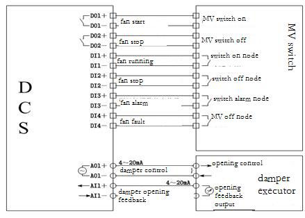
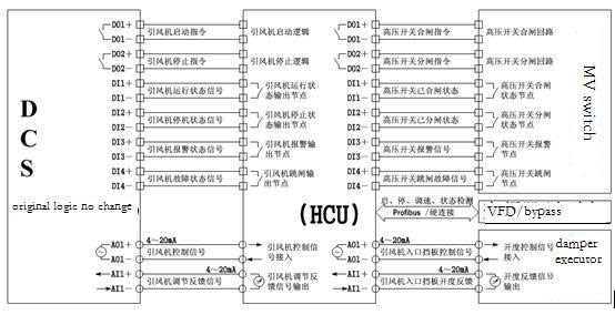
As a core of ID control system, coordination cabinet is installed with AC drive together in site. It works independently. When AC drive or control system is broken, HCU can ensure ID fan run in direct on line state. When HCU is broken, DCS will control MV switch and damper opening to make sure ID fan system safety.
There is no change in DCS interface. Operator controls ID fan start/stop in ID fan interface, controls air flow to keep pressure by damper. But, starting variable frequency state or direct on line state is identified by HCU according to bypass cabinet and AC drive status. Opening signal is converted to variable frequency speed signal to realize pressure stability.
Characteristics
1) DCS operation mode and quantity of ports keep same as before, no need to add hardware.
2) Original control logic of DCS keeps same. HCU exists as a equipment. DCS structure is simple and clear.
3) System operation mode keeps same. Operation mode of ID fans is realized by HCU, meanwhile, it accepts manual control, more flexible.
4) Stable hardware, strong operational power of software, high reliability; as safe as DCS.
5) Support I/O module changing on line, heat plug-pull, reduce stop time resulted from fault.
6) Configuration of AC drive, bypass cabinet and MV switch, coherent logic management;
7) In case of CPU or system powers off, HCU makes DCS control MV switch as well as other original line frequency equipment, which ensures safety and reliability.
A 100MW machinery unit is 380t/h coal powder furnace. The ID fan system is driven by two motors 6kV/800kW. In order to save energy, improve ID fan efficiency, reduce damper adjustment loss, user decides to choose stable and reliable AC drive reconstruction.
Because the DCS was changed for several times, the spare I/O ports are not enough for AC drive construction. There is a question that how to realize AC drive reconstruction without modification for DCS and control logic.
After deep research in AC drive characteristics, furnace operation technology and DCS structure, we put forward a new technology (HCU for abbreviation) which can save energy without modification for DCS and control logic.
Scheme
After analyzing furnace ID fan system, according to tenet of "safe and reliable, appropriate structure, easy operation, few change", we provide a one-drive-one manual bypass scheme. Please see following drawing:

QF: MV switch; QS: isolating switch; TF: AC drive; M; motor. Dashed border inside is newly added. QF and M are original equipments. QS12 and QS13 are mechanical and electrical interlocked to prevent AC drive output from being short circuit with 6kV. When ID fan needs to run in variable state, user closes QS11 and starts ID fan; when ID fan needs to run in direct on line state, user stops ID fan, opens QS12 and QS11, closes QS13, starts ID fan.
Principle
Before reconstruction, original control drawing is shown in following figure. DCS controls ID motor start/stop by controlling MV switch, controls furnace pressure by adjusting damper opening.

After reconstruction with AC drive, for routine design, it needs to add AC drive, bypass cabinet, switch equipment to connect control signals and status signals to DCS, realizing equipment control and variable frequency operation by changing DCS port and logic. Please see control principle drawing:

HCU technology is obvious simple in system structure, control logic and DCS ports. System configures MV switch, AC drive as a whole equipment through HCU, same function with original system, realizing ID fan start/stop and requirement of furnace pressure. HCU identifies fan operation mode according to dynamic system state, receives DCS start/stop signal for motor. Meanwhile, HCU coordinates speed, opening and pressure signal automatically as per operation mode. In this way, control characteristic keeps the same as present system, no need of changing DCS port, inside logic and interlock.

HCU configures AC drive, bypass cabinet and MV switch as a whole equipment, namely, for DCS, there is no problem of switch between variable frequency/direct on line, speed switch, opening switch, and interlock logic modification. Because ports between DCS and ID fan control device is not changed, original interlock and protection logic are still valid. HCU can identify fault points and security class automatically according to operation mode and equipment status, ensure correct signal to DCS, avoid mistake and no response.
Implementation
Before reconstruction, DCS communicates with control ports of ID fan, MV switch and other control devices. Its drawing is shown in figure 5. after reconstruction, DCS manages signals, distributes commands and controls objects through HCU. Its drawing is shown in following figure:


As a core of ID control system, coordination cabinet is installed with AC drive together in site. It works independently. When AC drive or control system is broken, HCU can ensure ID fan run in direct on line state. When HCU is broken, DCS will control MV switch and damper opening to make sure ID fan system safety.
There is no change in DCS interface. Operator controls ID fan start/stop in ID fan interface, controls air flow to keep pressure by damper. But, starting variable frequency state or direct on line state is identified by HCU according to bypass cabinet and AC drive status. Opening signal is converted to variable frequency speed signal to realize pressure stability.
Characteristics
1) DCS operation mode and quantity of ports keep same as before, no need to add hardware.
2) Original control logic of DCS keeps same. HCU exists as a equipment. DCS structure is simple and clear.
3) System operation mode keeps same. Operation mode of ID fans is realized by HCU, meanwhile, it accepts manual control, more flexible.
4) Stable hardware, strong operational power of software, high reliability; as safe as DCS.
5) Support I/O module changing on line, heat plug-pull, reduce stop time resulted from fault.
6) Configuration of AC drive, bypass cabinet and MV switch, coherent logic management;
7) In case of CPU or system powers off, HCU makes DCS control MV switch as well as other original line frequency equipment, which ensures safety and reliability.
Post a Comment:
You may also like:

