Category
- Products
-
- FAQ
- Contact us

AC Drive Manufacturer
How does an AC Drive Control Induction Motor Speed?
For an induction motor, rotor speed, frequency of the voltage source, number of poles and slip are interrelated according to the following equation:
n: mechanical speed (rpm)
f1: fundamental frequency of the input voltage (Hz)
p: number of poles
s: slip
The analysis of the formula above shows that the mechanical speed of an induction motor is a function of three parameters. Thus the change of any of those parameters will cause the motor speed to vary as per the table below.
The utilization of AC drives comprehends currently the most efficient method to control the speed of induction motors. AC drives transform a constant frequency constant amplitude voltage into a variable (controllable) frequency-variable (controllable) amplitude voltage. The variation of the power frequency supplied to the motor leads to the variation of the rotating field speed, which modifies the mechanical speed of the machine.
The torque developed by the induction motor follows the equation below:
T: torque available on the shaft (N.m)
φm: magnetizing flux (Wb)
I2: rotor current (A) → depends on the load!
V1: stator voltage (V)
k1 e k2: constants → depend on the material and on the machine design!
Considering a constant torque load and admitting that the current depends on load (therefore practically constant current), then varying proportionally amplitude and frequency of the voltage supplied to the motor results in constant flux and therefore constant torque while the current remains unchanged. So the motor provides continuous adjustments of speed and torque with regard to the mechanical load. Losses can be thus minimized in accordance with the load conditions by keeping the slip constant at any speed, for a given load.
The curves below are obtained from the equations above.

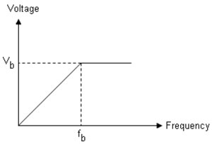
The ratio V1/f1 is kept constant up to the motor base (rated) frequency. From this frequency upwards the voltage is kept constant at its base (rated) value, while the frequency applied on the stator windings keeps growing, as shown next.
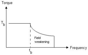
Thereby the region above the base frequency is referred to as field weakening, in which the flux decreases as a result of frequency increase, causing the motor torque to decrease gradually. The typical torque versus speed curve of an AC drive fed induction motor is illustrated below.

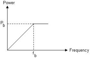
It comes out that torque is kept constant up to the base frequency and beyond this point it falls down (weakening field). Since the output is proportional to torque times speed, it grows linearly up to the base frequency and from that point upwards it is kept constant. This is summarized by the graph beside.

The number of variable frequency applications controlled by means of an AC drive has increased significantly over the recent years. This may be explained by the many benefits provided by such applications:
n = 120 f1 (1 - s) / pWhere
n: mechanical speed (rpm)
f1: fundamental frequency of the input voltage (Hz)
p: number of poles
s: slip
The analysis of the formula above shows that the mechanical speed of an induction motor is a function of three parameters. Thus the change of any of those parameters will cause the motor speed to vary as per the table below.
|
Speed Control |
|
|
Parameter |
Application characteristics |
|
Number of poles |
Discrete variation |
|
Oversizing |
|
|
Slip |
Continuous variation |
|
Rotor losses |
|
|
Limited frequency range |
|
|
Voltage frequency |
Continuous variation |
|
Utilization of AC drives |
|
The utilization of AC drives comprehends currently the most efficient method to control the speed of induction motors. AC drives transform a constant frequency constant amplitude voltage into a variable (controllable) frequency-variable (controllable) amplitude voltage. The variation of the power frequency supplied to the motor leads to the variation of the rotating field speed, which modifies the mechanical speed of the machine.
The torque developed by the induction motor follows the equation below:
T = k1. fm. I2Despising the voltage drop caused by the stator impedance, the magnetizing flux is found to be:
φm = k2. V1 / f1Where
T: torque available on the shaft (N.m)
φm: magnetizing flux (Wb)
I2: rotor current (A) → depends on the load!
V1: stator voltage (V)
k1 e k2: constants → depend on the material and on the machine design!
Considering a constant torque load and admitting that the current depends on load (therefore practically constant current), then varying proportionally amplitude and frequency of the voltage supplied to the motor results in constant flux and therefore constant torque while the current remains unchanged. So the motor provides continuous adjustments of speed and torque with regard to the mechanical load. Losses can be thus minimized in accordance with the load conditions by keeping the slip constant at any speed, for a given load.
The curves below are obtained from the equations above.

The ratio V1/f1 is kept constant up to the motor base (rated) frequency. From this frequency upwards the voltage is kept constant at its base (rated) value, while the frequency applied on the stator windings keeps growing, as shown next.
Thereby the region above the base frequency is referred to as field weakening, in which the flux decreases as a result of frequency increase, causing the motor torque to decrease gradually. The typical torque versus speed curve of an AC drive fed induction motor is illustrated below.

It comes out that torque is kept constant up to the base frequency and beyond this point it falls down (weakening field). Since the output is proportional to torque times speed, it grows linearly up to the base frequency and from that point upwards it is kept constant. This is summarized by the graph beside.

The number of variable frequency applications controlled by means of an AC drive has increased significantly over the recent years. This may be explained by the many benefits provided by such applications:
- Aloof control – the control can be installed remotely at a suitable location, keeping just the motor in the processing area – on the contrary of hydraulic and mechanical varying speed systems.
- Cost reduction – direct on line starting of induction motors cause current peaks that harm the motor as well as other electric equipments linked to the electrical system. AC drive provides soft starting, resulting in cost reduction with regard to maintenance.
- Gain of productivity – industrial systems are often oversized due to an expectation of future production increase. AC drives allow the proper regulation of the operational speed according to the equipments available and the production needs.
- Energy Efficiency – the power system global efficiency depends not only on the motor, but also on the control. AC drives are high efficiency apparatuses, reaching typically 97% or more. Induction motors also present high efficiency levels, reaching up to 95% or even more in larger machines operating at rated conditions. When speed variation is required, the output changes in an optimized way, directly affecting the energy consumption and leading to high efficiency levels performed by the system (variable frequency drive + motor).
- Versatility – AC drives suit both variable and constant torque loads. With variable torque loads (low torque demand at low speeds) the motor voltage is decreased to compensate for the efficiency reduction normally resultant from load reduction. With constant torque (or constant power) loads the system efficiency improvement comes from the feasibility of continuous adjustment of speed, with no need to use multiple motors or mechanical variable speed systems (such as pulleys and gears), which introduce additional losses.
- High quality – the accurate speed control obtained with AC drives results in process optimization, providing a final product of better quality.
Post a Comment:
You may also like:

